Article: Blocks method, constructing a hand through differentiation method.
HAND CONSTRUCTION IN BLENDER
In this interactive article we will need lot of geometric parameters. For constructing hands or other hard constrained forms we need to stablish several considerations. All references can be powerfull tools but first we need to start strictly in parts and step by step.
Hands are perfect tools, but are complex in physionomy, so depending who is the owner, there are different morphologies and shapes for hands. This article deals about human hands, but, may be useful for other kind of hands.
The main shape we think would be top shape, that ironically is very easy. But realistic hand construction is the most difficult to achieve. For this we have to build different constraints for hand mesh, and they could be:
- Boundary or principal outline (you can use a background image, but in this tutorial is optional the use of your own hand reference)
- Main pivots for all finger links.
- Generic cross sections for different planes (xy, yz or xz).
- Set level for knuckles and wrist height positions ..
- Set pivots for thumb for flat pose..
Note:
- I'm using most of geometries to only to fix main features for this model, so it is intended only for references and for nothing else.
- When I say vectorial I'm referred as a term artistic usage, then only sense and direction are implicit.
BOUNDARY OR CROSS SECTION
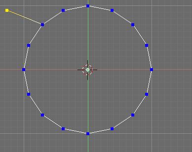
First, we need construct the 2d form of a hand. Fire up Blender!... in top view create a circle with 16 vertices and in edit mode create the fingers by extruding some vertices. And do some adjust to create a good hand shape
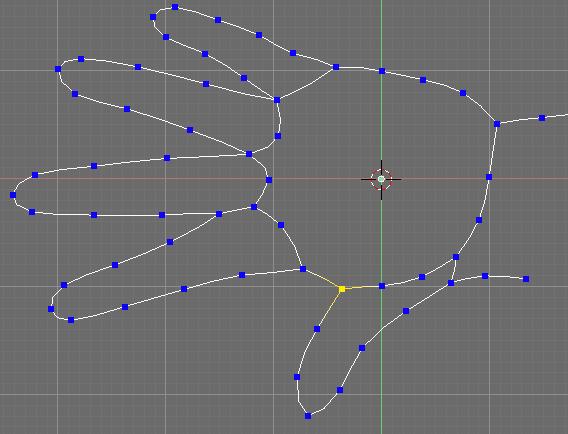
When you are done move the vertices to create the hand boundary. Boundary will constraint pivots for the whole stuff and final mesh. Focus to the outline construction as above for the pointer finger. Pointer finger will be the image of other fingers.
Add subsurf modifier and select the option 'apply modifier to editing cage during edit mode'. This option will smooth our wires like NURBS does, but subsurf modifier gives the advantage for splines by having the control points inside of themselves.
Add some edges to create primitive axes that will be reference for future pivots.
Duplicate the original wires and create 2 arrays above and below [L key for select linked geometry]. Actually this shape has a function of reference, but for next procedure will transfer its function from reference to geometry..
Select the structure that belongs to pointer finger and [shif+D key] to duplicate, [press P key] to separate the new wires. Exit edit mode and select the new wires you create and move them to other layer.
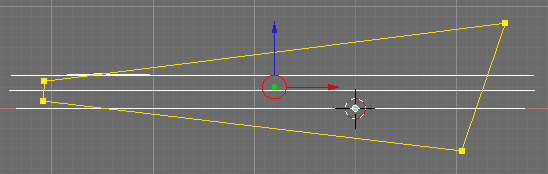
GENERIC CROSS SECTIONS FOR DIFFERENT PLANES
On the front view create a shape like this to constraint the profile outline of hand.
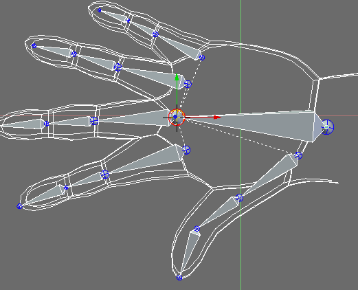
MAIN PIVOTS FOR ALL FINGER LINKS.
Create an armature for hand, with armature still selected enter to edit mode and starting building on bones by extruding them first from the wrist.
Then locate the bone tip at the big finger base and extrude to create 3 links for this finger. Select the last 3 links you create and duplicate 4 times for the fingers that remain, Locate the links at the axis centers.
...
Check link proportions, the first link (in this case bone called pointerlink1 must have the same lenght that the next two links together (fingers end at the knuckles area but they fuse together with flesh at middle lenght).
Now, use the wire used as pivot reference by selecting the vertices that belong to a each axis edge and position the cursor at the center.
Now in edit mode select the main pivots for bones, then snap them into the cursor.
SET LEVEL FOR KNUCKLES AND WRIST HEIGHT POSITIONS.
Select again links for big finger on front or side view move them up a little.
Now select the pinky links and move them down a little in front or side view. The pinky knuckle on reality can move a bit and can move a bit more than ring finger, so the little traslation is just a little rotation about the hand main axis (Actually the hand body bone). So if you're thinking to pose it you must rotate about some point of this bone, even unstressed this finger has a little degree lean toward the center hand.
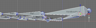
Set the level position for wrist by selecting the hand body pivot (HandBodyBone) and the first tumb link pivot. In fact it should to set all the levels for the hand follow your own real hand.
Shape of 2d hand will bear the boundary for future hand mesh, the nuckles position will give the position for fingers.
Continue and exit edit mode to object mode and move the armature to another layer. Now go to the layer where the pointer mesh is, and select it..
Disable 'enable modifier during interactive display' for back to solid wires. Enter edit mode and move the upper and downer vertices to give a good cross section shape as the way to construct the pointer finger.
Move the vertices as the image above for the nail area and start to skin the wires (similar than NURBS surfaces do). For the center structure delete the axis edges. Remember to skin rationally on quad forms.
Add some more edges on top part as above
At the bottom create subdivided areas and skin. Select the edge shown and subdivide it.
Select new vertex you just created and pull it down.
Now to create a nail we go to use extrude tool by selecting the faces shown as above.
Press [E key] to extrude and select region, press Esc key to cancel and scale a bit the new faces you created.
Once again extrude up the region a bit. Scale out a little the new region..
Select the resulting lateral new faces shown above and extrude them a bit.
With little adjustments, you'll have a similar form.
Skinning is a fine method for difficult meshes, but for more detail it will be applied the pangea method for pointer finger.
Duplicating and shatter the original mesh.
Next, duplicate and separate in sections the tip and back sections, and move them to a new layer..
With the new objects you create select the mesh shown above and enter edit mode. Select the vertices shown and move them backwards. Use top view to positioning better these vertices.
Back to solid wires for the two meshes and extrude the vertices 2 times forward: the first time forward and low them a bit, extrude again and up. The vertices that form a V on the extremes you must select the vertices inside of the V and create a face.
Adjust some vertices for smooth the new form and skin the new geometry.
Now, select the pointer tip and move the vertices shown forward.
Extrude the selected vertices backwars 3 times backwards as above and create new faces skinning.
The secuence above shown a recommended skinning procedure.
Do the same for the other extreme to complete the part. Exit edit mode and select the other mesh for resume editing.
Select the vertices shown and extrude on a W form
A W extruded form
Now create new faces for V forms.
k
Skin the flying edges.
Press F7 and in the Draw panel select 'Wire' for Drawtype settings.
Move the vertices shown and locate just up of the pointer pivot shown. This procedure ensures a good deformation with armatures
Select the center vertices for this new geometry and scale them
The form for this geometry must be like a crater.
Select the bottom vertices of the same cross section, move them forward
Extrude 3 times as above and apply once again the last procedures.
Once you have finish do some vertex adjustment you can smooth the whole mesh to ensure that the mesh has a smooth form. Next we will create the fingers base.
The function of these object is reference geometry that has a potential for new geometry creation.
OPTIONAL
Continue the last session or open Standard_Hand_Model_1.blend. Go to Right view (ortho) by press [3] of numeric pad and Add>>Curve>>NURBS Circle and enable 'Allow Curve be 3d, it doesn't fill then' setting 3d button on Curve and Surface panel. Modify the curve shape as above and in edit mode scale it. Name it C on the Object Name field.
Selec the armature and edit mode select the pointer base pivot and move the cursor there [Shift+S key]. Exit edit mode, and in a new layer go to ortho top view and Add>>Curve>>Path to create a path curve.
Set the Order U: 2 for reduce the control points to 2 and on 3d window delete the three inner vertices for this path
Select the rightmost vertex and [Shift+S key] to Snap it into the cursor.
Type C on BevOb field of Curve and Surface panel to get the curve shape from the cross section named C. Next you must put the leftmost vertex of the path over the next link pivot to get the base section for pointer finger
Duplicate the new object and locate these object over the other fingers. For pinky finger duplicate the cross section you create two more times and rename them with P and T letters. In Edit mode change the size of each and rotate them a little.
. Change the bevel shape for pinky and Thumb fingers by typing P and T respectively on BevOb fields This geometry is only directional reference.
Select the pointer mesh shown above and select the rightmost vertices.
On top view extrude this section backwars to the middle lenght of the link. Join the tip pointer to the rear mesh. Follow the boundary we made originally to constraint the profile outline of orthogonal front view and scale the thickness of pointer finger
s
Again extrude to create a finger base ridge and skin again.
CREATING THE OTHER FINGERS
At this point you can add more details to your pointer finger until make it highly detailed, joints are widther than the common cross section for fingers, for the wrinkles of the fingers you can dettach the crater created before and continue adding details to it, or you can choose leave it so. The pangea II method is reversible on whatever stage it is and you can add details later, creating new mesh parts and applying transposition..
Select the pointer knuckle pivot to positioning the cursor there, select the new mesh you create and press [Bar] on the dialog choose transform>>center cursor. On top view, duplicate the mesh 3 times and locate them over each knuckle and edit each mesh scaling, rotating, mirroring Ring and Pinky fingers and adapting by fitting the meshes into the hand shape. Follow the direction reference for pinky finger and rotate it a bit.
CREATING THE PUNCH.
We going to resolve with merging and flow comb
Select the hand shape and select the palm vertices shown, duplicate and separate them.
Extrude the new shape to create a bevel, and remove subsurf modifier.
Create a cylinder of 6 vertices and duplicate it 3 times for create the base for each finger and snap them as you snap the fingers. Do the necessary changes to the bevel mesh and move a little forwards. Select all cylinders and with booleans select the union option, delete the original cylinders. Select the unified cylinders and then the rear mesh and with booleans tools unify and delete original meshes.
The result will be a little confuse but we going to comb the flow and make some adjusto to the mesh shape. Decimate a little (0.700) and apply. The flow comb can require lot of time but is effective. You must start on the knucles area reshaping and creating rhomboses that laid just above of each knucke pivots. You have to merge, subdivide, rotate edges, etc, The flow for fingers must have straight lines
Apply subsurf modifier and make sure that the rhombuses are well looking. Rhombuses must have wires that attach them in between, and these wires must be subdivided. The result you may have it different, but you maus practice the way good meshes have edge and vertex structures, how you can improve these meshes.
Punch is one of the most dynamic part and you must have a good flow for the base fingers
For the area between the fingers the flow of edges and vertices must be a similar as the shown above
n
Select the hand body (that comes in Standard_Hand_Model_1.blend) and attach to the punch [Control+J key]. Merge vertices and delete some vertices if are confuse, you only have to create a single mesh, and after you can add more changes.
Try to attach the fingers and make changes for the topology. The result you can see in Standard_Hand_Model_2.blend, this model is not over yet but it can help you to understand of a good flow.,
To create the remaining geometry you should follow the last procedures. For the thumb you must create a pentagon section for the medium cross section and duplicate a finger tip and scale for create the thumb tip. For the creation of palm ridges you must shatter the hand body into a high part and palm and edit it. The ridges lay below the knuckles and thumb ridge is folded on the end of the super adductor thumb muscle.
When you are done is good idea to select all vertices [W key]>>SPECIALS>>Smooth. Move some vertices to adjust
As you see, solving through booleans is a little boring procedure but not at all. You can create similar geometry by extruding vertices and wiring but you could spent too much time. So, the boolean technic is an analogy of 2d artist when merge two shapes into one that have the original feature
What about the other hand tutorials???. Each tutorial has its own procedure, but the choice you make at last, better is to benchmark all options into a better one. Even the pangea II method works on finished models, and you still can mate the better features into a single mesh.
The next links are complements for this tutorial and the better example for resolution needs.
Hand tutorial complement (external link)
Body Parts
Skin procedures link1
Happy blending!