martes, 16 de noviembre de 2010

Organic Modeling

ORGANIC MODELING METHODS.

Usually we use lots of actual modeling features I will put a list of features related with the whole modeling stuff

TRADITIONAL METHODS

Ancient but yet used awckard modeling:

VERT BY VERT

BORING AND MANIPULATING GIZMOS

NEW AND IMPROVED METHODS


BLOCKS METHOD
CLAY SCULPING

RETOPOLOGY TOOLS

DECIMATION

TESSELATION

BOOSTER METHODS OF MODELING
  • Voxelization with Sculptris
  • .......
BENCHMARK PIPELINE

sábado, 13 de noviembre de 2010

Modeling Through Outlines to a Highly Constrained Form

Article: Blocks method, constructing a hand through differentiation method.

HAND CONSTRUCTION IN BLENDER

In this interactive article we will need lot of geometric parameters. For constructing hands or other hard constrained forms we need to stablish several considerations. All references can be powerfull tools but first we need to start strictly in parts and step by step.

Hands are perfect tools, but are complex in physionomy, so depending who is the owner, there are different morphologies and shapes for hands. This article deals about human hands, but, may be useful for other kind of hands.

The main shape we think would be top shape, that ironically is very easy. But realistic hand construction is the most difficult to achieve. For this we have to build different constraints for hand mesh, and they could be:
  • Boundary or principal outline (you can use a background image, but in this tutorial is optional the use of your own hand reference)
  • Main pivots for all finger links.
  • Generic cross sections for different planes (xy, yz or xz). 
  • Set level for knuckles and wrist height positions ..
  • Set pivots for thumb for flat pose..
Note:

  1. I'm using most of geometries to only to fix main features for this model, so it is intended only for references and for nothing else. 
  2. When I say vectorial I'm referred as a term artistic usage, then only sense and direction are implicit.

BOUNDARY OR CROSS SECTION

First, we need construct the 2d form of a hand. Fire up Blender!... in top view create a circle with 16 vertices and in edit mode create the fingers by extruding some vertices. And do some adjust to create a good hand shape


When you are done move the vertices to create the hand boundary. Boundary will constraint pivots for the whole stuff and final mesh. Focus to the outline construction as above for the pointer finger. Pointer finger will be the image of other fingers.


Add subsurf modifier and select the option 'apply modifier to editing cage during edit mode'. This option will smooth our wires like NURBS does, but subsurf modifier gives the advantage for splines by having the control points inside of themselves.


Add some edges to create primitive axes that will be reference for future pivots.


Duplicate the original wires and create 2 arrays above and below [L key for select linked geometry]. Actually this shape has a function of reference, but for next procedure will transfer its function from reference to geometry..


Select the structure that belongs to pointer finger and [shif+D key] to duplicate, [press P key] to separate the new wires. Exit edit mode and select the new wires you create and move them to other layer.

GENERIC CROSS SECTIONS FOR DIFFERENT PLANES


On the front view create a shape like this to constraint the profile outline of hand.

MAIN PIVOTS FOR ALL FINGER LINKS.


Create an armature for hand, with armature still selected enter to edit mode and starting building on bones by extruding them first from the wrist.


 Then locate the bone tip at the big finger base and extrude to create 3 links for this finger. Select the last 3 links you create and duplicate 4 times for the fingers that remain, Locate the links at the axis centers.


...
Check link proportions, the first link (in this case bone called pointerlink1 must have the same lenght that the next two links together (fingers end at the knuckles area but they fuse together with flesh at middle lenght).


Now, use the wire used as pivot reference by selecting the vertices that belong to a each axis edge and position the cursor at the center.


 Now in edit mode select the main pivots for bones, then snap them into the cursor.

SET LEVEL FOR KNUCKLES AND WRIST HEIGHT POSITIONS.


Select again links for big finger on front or side view move them up a little.


Now select the pinky links and move them down a little in front or side view. The pinky knuckle on reality can move a bit and can move a bit more than ring finger, so the little traslation is just a little rotation about the hand main axis (Actually the hand body bone). So if you're thinking to pose it you must rotate about some point of this bone, even unstressed this finger has a little degree lean toward the center hand. 


Set the level position for wrist by selecting the hand body pivot (HandBodyBone) and the first tumb link pivot. In fact it should to set all the levels for the hand follow your own real hand.


Shape of 2d hand will bear the boundary for future hand mesh, the nuckles position will give the position for fingers.

Continue and exit edit mode to object mode and move the armature to another layer. Now go to the layer where the pointer mesh is, and select it..
Disable 'enable modifier during interactive display' for back to solid wires. Enter edit mode and move the upper and downer vertices to give a good cross section shape as the way to construct the pointer finger.


Move the vertices as the image above for the nail area and start to skin the wires (similar than NURBS surfaces do). For the center structure delete the axis edges. Remember to skin rationally on quad forms.


Add some more edges on top part as above


At the bottom create subdivided areas and skin. Select the edge shown and subdivide it.


Select new vertex you just created and pull it down.


Now to create a nail we go to use extrude tool by selecting the faces shown as above.


Press [E key] to extrude and select region, press Esc key to cancel and scale a bit the new faces you created.


Once again extrude up the region a bit. Scale out a little the new region..
Select the resulting lateral new faces shown above and extrude them a bit.
With little adjustments, you'll have a similar form.


Skinning is a fine method for difficult meshes, but for more detail it will be applied the pangea method for pointer finger.

Duplicating and shatter the original mesh.
Next, duplicate and separate in sections the tip and back sections, and move them to a new layer..
With the new objects you create select the mesh shown above and enter edit mode. Select the vertices shown and move them backwards. Use top view to positioning better these vertices.
Back to solid wires for the two meshes and extrude the vertices 2 times forward: the first time forward and low them a bit, extrude again and up. The vertices that form a V on the extremes you must select the vertices inside of the V and create a face.
Adjust some vertices for smooth the new form and skin the new geometry.
Now, select the pointer tip and move the vertices shown forward.
Extrude the selected vertices backwars 3 times backwards as above and create new faces skinning.
The secuence above shown a recommended skinning procedure.
Do the same for the other extreme to complete the part. Exit edit mode and select the other mesh for resume editing.
Select the vertices shown and extrude on a W form
A W extruded form
Now create new faces for V forms.
k
Skin the flying edges.
Press F7 and in the Draw panel select 'Wire' for Drawtype settings.
Move the vertices shown and locate just up of the pointer pivot shown. This procedure ensures a good deformation with armatures
Select the center vertices for this new geometry and scale them
The form for this geometry must be like a crater.
Select the bottom vertices of the same cross section, move them forward
Extrude 3 times as above and apply once again the last procedures.
Once you have finish do some vertex adjustment you can smooth the whole mesh to ensure that the mesh has a smooth form. Next we will create the fingers base.
The function of these object is reference geometry that has a potential for new geometry creation.
OPTIONAL
Continue the last session or open Standard_Hand_Model_1.blend. Go to Right view (ortho) by press [3] of numeric pad and Add>>Curve>>NURBS Circle and enable 'Allow Curve be 3d, it doesn't fill then' setting 3d button on Curve and Surface panel. Modify the curve shape as above and in edit mode scale it. Name it C on the Object Name field.
Selec the armature and edit mode select the pointer base pivot and move the cursor there [Shift+S key]. Exit edit mode, and in a new layer go to ortho top view and Add>>Curve>>Path to create a path curve.
Set the Order U: 2 for reduce the control points to 2 and on 3d window delete the three inner vertices for this path
Select the rightmost vertex and [Shift+S key] to Snap it into the cursor.
Type C on BevOb field of Curve and Surface panel to get the curve shape from the cross section named C. Next you must put the leftmost vertex of the path over the next link pivot to get the base section for pointer finger
Duplicate the new object and locate these object over the other fingers. For pinky finger duplicate the cross section you create two more times and rename them with P and T letters. In Edit mode change the size of each and rotate them a little.
. Change the bevel shape for pinky and Thumb fingers by typing P and T respectively on BevOb fields This geometry is only directional reference.
Select the pointer mesh shown above and select the rightmost vertices.
On top view extrude this section backwars to the middle lenght of the link. Join the tip pointer to the rear mesh. Follow the boundary we made originally to constraint the profile outline of orthogonal front view and scale the thickness of pointer finger
s
Again extrude to create a finger base ridge and skin again.
CREATING THE OTHER FINGERS
At this point you can add more details to your pointer finger until make it highly detailed, joints are widther than the common cross section for fingers, for the wrinkles of the fingers you can dettach the crater created before and continue adding details to it, or you can choose leave it so. The pangea II method is reversible on whatever stage it is and you can add details later, creating new mesh parts and applying transposition..
Select the pointer knuckle pivot to positioning the cursor there, select the new mesh you create and press [Bar] on the dialog choose transform>>center cursor. On top view, duplicate the mesh 3 times and locate them over each knuckle and edit each mesh scaling, rotating, mirroring Ring and Pinky fingers and adapting by fitting the meshes into the hand shape. Follow the direction reference for pinky finger and rotate it a bit.
CREATING THE PUNCH.
We going to resolve with merging and flow comb
Select the hand shape and select the palm vertices shown, duplicate and separate them.
Extrude the new shape to create a bevel, and remove subsurf modifier.
Create a cylinder of 6 vertices and duplicate it 3 times for create the base for each finger and snap them as you snap the fingers. Do the necessary changes to the bevel mesh and move a little forwards. Select all cylinders and with booleans select the union option, delete the original cylinders. Select the unified cylinders and then the rear mesh and with booleans tools unify and delete original meshes.

The result will be a little confuse but we going to comb the flow and make some adjusto to the mesh shape. Decimate a little (0.700) and apply. The flow comb can require lot of time but is effective. You must start on the knucles area reshaping and creating rhomboses that laid just above of each knucke pivots. You have to merge, subdivide, rotate edges, etc, The flow for fingers must have straight lines
Apply subsurf modifier and make sure that the rhombuses are well looking. Rhombuses must have wires that attach them in between, and these wires must be subdivided. The result you may have it different, but you maus practice the way good meshes have edge and vertex structures, how you can improve these meshes.
Punch is one of the most dynamic part and you must have a good flow for the base fingers
For the area between the fingers the flow of edges and vertices must be a similar as the shown above
n
Select the hand body (that comes in Standard_Hand_Model_1.blend) and attach to the punch [Control+J key]. Merge vertices and delete some vertices if are confuse, you only have to create a single mesh, and after you can add more changes.
Try to attach the fingers and make changes for the topology. The result you can see in Standard_Hand_Model_2.blend, this model is not over yet but it can help you to understand of a good flow.,
To create the remaining geometry you should follow the last procedures. For the thumb you must create a pentagon section for the medium cross section and duplicate a finger tip and scale for create the thumb tip. For the creation of palm ridges you must shatter the hand body into a high part and palm and edit it. The ridges lay below the knuckles and thumb ridge is folded on the end of the super adductor thumb muscle.
When you are done is good idea to select all vertices [W key]>>SPECIALS>>Smooth. Move some vertices to adjust
As you see, solving through booleans is a little boring procedure but not at all. You can create similar geometry by extruding vertices and wiring but you could spent too much time. So, the boolean technic is an analogy of 2d artist when merge two shapes into one that have the original feature
What about the other hand tutorials???. Each tutorial has its own procedure, but the choice you make at last, better is to benchmark all options into a better one. Even the pangea II method works on finished models, and you still can mate the better features into a single mesh.
The next links are complements for this tutorial and the better example for resolution needs.


Hand tutorial complement (external link)
Body Parts
Skin procedures link1
Happy blending!


jueves, 11 de noviembre de 2010

Amoo (character)

Actually this 3d model is taken from a real person, a damn dear friend of mine.......so it is expected that she is go to be the starring of this movie trailer.

Advertisement.

Some people think I've edited a previous 3d model, a model as victoria, makehuman, or another crappy character but the truth is that I`ve made this model from scratch some years before (see Amoo Model History and in another article I'll post her topology evolution), some time has taken to be as seen in some pictures posted here and I proud of.

Actually I`ve used lot of references, some of these are pictures, 3d models, reasonings of logic, no logic and topology.

Main references are taken from pictures and drawings.


 Some references are taken from other pictures from same model from different version of itself to create a continous feedback and to take the best of old and new.


Actually this character has uv maps from other characters..............perhaps need a more refined topology for good uv unwrapping

------------------------------------------ Index -----------------------------------------------------

domingo, 31 de octubre de 2010

3d Blender Workshop


Articles and workshops mostly for blender as principal platform

Some time ago I started learning 3d tools to satisfy lot of projects i just got in mind. So this blog is intended to be almost all about, I've produced out many kinds of essays, tutorials and articles to share and I go to start them. Some of them were written long time ago but if this space allows me to organize them good, I think they will help you in some way....

This page is under construction and is continuosly changing...sorry if you have some inconveniences for it, but if you have questions you can contact me at ericck82@yahoo.com.mx

Advertisement:

When I say essays, means what I do speak with only my point of view
When I say tutorials, means what I do follow whatever methodology as usual in blender
When I say articles, means what I do things yet proved and with potential of improving in some way the actual pipeline workflow.

Modeling


Rigging

  • bla
Other Articles
Oh Yes -Feedback!-

  • Forums
  • C&C
About

  • summary
  • More About Me
  • More Workshops

Those damn rigs

Today in blender and similar comunities you'll find a huge library of characters and animation files. Many of them are excellent rigs. Wow!!!!!!! you'd say and even me either........ but I am not convinced at all cause in my point of view there are still some unnatural features in final animations. What can we do???. Dont get me wrong, these rigs are references for all rigs that follow including my ones but there are some things that need to go better.

What the heck!!!!

Snooping around several blogs and studying theirs rigs like mancandy and rigs recently made by lot of artists have many mistakes. Really have we a decent standard rig today? You betcha but these need some lot of constraint and references I think......who's with me? I just know my confusion is growing more and more.......

I think we need a better understanding of critical pivots and how to locate them, an example of what I do mean can be this: the beggining of neck bones in mostly cases are incorrect so animations are still rigid

Some helpfull Solutions

Some mocap files feature vectorial references that made more realistic the movement, so think about follow these good references and afterwards adding some other better features found in Mancandy and Miku rigs............I need extend more this article.........


MOCAP animation note multiple IK Targets..........some of them adjust to mean movement..

page under construction


--------------------------------------- Index ------------------------------------------------------------

domingo, 10 de octubre de 2010

Cephis Project

CEPHIS PROJECT

Cephis is a project primarly addressing to learn best animation techniques based on a sort medieval tale no yet finally redacted. This project comes with a movie trailer format which has few but well defined characters................

CEPHIS TITLE

This is the title for final movie trailer.

The movie trailer will last about 2 minutes

CEPHIS TITLE SUMMARY

A space dweller survives from destruction of his mother spaceship in course to an earth colony. But his return voyage to safety point suffers some pulls out of adjustments becoming without knowledge about a time travel to the home planet, it will pass some time to discover he really is in another epoch or in some strange place different to his home.

MORE ABOUT CEPHIS PROJECT

The starring, Amoo a lonely princess looking for flee from a shattered kingdom result of lust of power and chaos. She will gonna find it with a help of a foreign man that wears and uses sofisticated weapons, but her sister Moora likes to avoid and struggles to trowing out all Amoo's plans, then Moora will want keep the outlander to her side to give her more power and some other treasures beyond all comprehension.

CAST OF CHARACTERS
(See cast of characters for more information)
Actually characters, props and scenarios are under development. ......

  • Paulette Yudelf as Amoo
  • Katrina Sonz as Moora
  • Ken Stewart as Leonard Kenneth
  • ..........
  • .........


------------------------------- Index ----------------------------------------------------------

CG Artist (About)

Erick Ramirez is a freelance 3d modeler


I started my studies about CAD y CG in 2004, the objective were investigation and development for low budget prosthesis, so I got skills and some sort of combination among software and format interoperatibility that deals with 3d programs.

My favorite platforms are:

Solid Edge: the best tool for part edit, assembly lines, parametric solids, parts family planning, assembly constraints and motion, features concurrent engineering in one application, among other improvement targets.

E machine Shop: gives process engineer tools, schedules, estimated budgets and materials, and a good 2d editor

Autocad: provide tools based in multiple measure systems, also traditional work methods based on layouts. Al contrario de ser una herramienta primaria la utilizo como complemento de Solid Edge

NX: una de mis herramientas favoritas para el analisis estructural, ademas para la planeacion de los procesos manufacturables sobre las partes. Igualmente es un gran complemento de Solid Edge

3ds Max: la herramienta complementaria para Autocad ademas para creacion de multiples modelos.

Blender: La plataforma mas util para creacion de formas parametricas, formas organicas, patrones, animacion, renderizado, visualizacion, entre muchas opciones mas, y lo mejor casi no tiene problemas de compatibilidad entre versiones y plataformas similares......................................................................................................

DAZ Studio: la utilizo como complemento de blender para simular y comparar los modelos y sus respectivas topologias.

Inkscape: la utilizo como complemento para blender y para creacion de objetos 2d vectoriales

The Gimp: un programa similar a Photoshop para el retoque de fotografias


A lo largo del nacimiento y desarrollo de este nuevo espacio ire publicando archivos multimedia y otros topicos relacionados a este blog, al igual que ire añadiendo vinculos relacionados y mucho mas.........por el momento la pagina estara en un solo idioma, en forma de borrador, lluvia de ideas, tormenta de ideas tornado de ideas blah, blah, blahhhhhh!!!!!!!!!!!!!!!.

MAS SOBRE MI PERFIL DE ARTISTA CG

Aqui una imagen de mi yo digital (necesito mejorarme un poco pero mi intencion es hacerme mas feo...........


En CG society tengo un pequeño espacio, mi avatar, nickname o aka es megastor 'erick ramirez'. Espacio el cual no he sacudido de polvo en un buen rato, en este espacio se muestran algunos trabajos hechos en 3d, algunos retocados en photoshop:

Tengo tambien un espacio por...........smoothdevil.......es un portafolio con el avatar de megastor tambien 'erick ramirez' -incluye mi foto- . Espacio igualmente que no he actualizado en el cual muestro mis habilidades en cg art:

por aqui tengo mas.......segun mi resumè escribi hace un tiempo 4 articulos para la revista blenderart magazine, desafortunadamente estaba tan concentrado en los articulos que no escribi mi direccion electronica. Estos articulos 'rigging a frog' 'managing metaballs' se pueden checar online en:

Otros dos articulos 'amateur mechanisms' y 'solid device construction' se encuentran en la siguiente entrega:

MODELADO ORGANICO

Es la parte mas maravillosa del diseño, intentar una forma e intentar lograrla bien, para ello tienes que poner en practica muchas herramientas y muchos metodos, en este espacio muy pronto colocare algunos tutoriales que jamas publique. Actualmente me desempeño bien creando creaturas fantasticas, todas requieren sus detalles que explicare mejor con el tiempo, se supone en esta parte de mi blog debo DAR UNA RESEÑA CON LOS CASOS MAS ILUSTRATIVOS Y CON MUCHOS LINKS!!!!!!!!!!!!!!!!!!

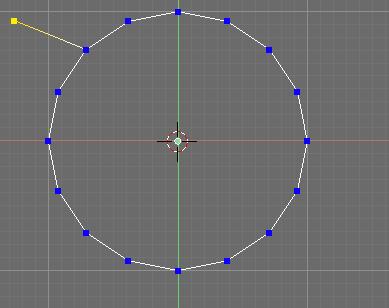
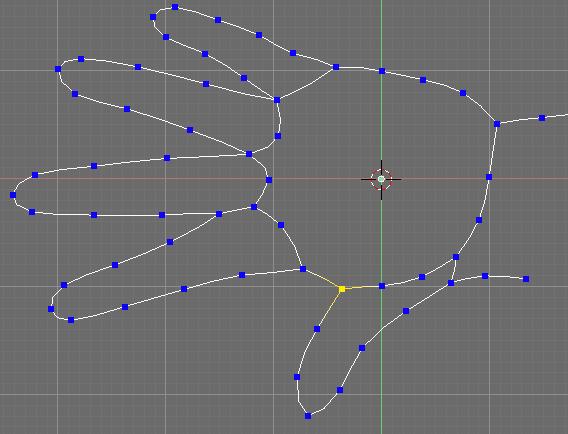
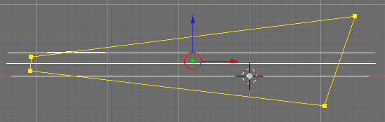
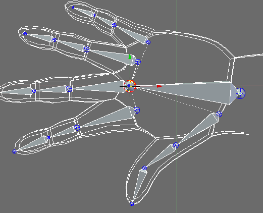
Las plataformas mas valiosas para el modelado organico son las que ayudan a esculpir formas libres. Como primer objetivo si se parte de 0 se debe obtener la forma mas basica del modelo a realizar, en este caso blender, luego se aplica el modulo de multiresolucion encontrando la mejor resolucion para realizar algo de detalles, se utiliza el modo esculpir mas la edicion manual, una vez que esta realizada la forma se procede a hacer la retopologia nuevamente con formas muy basicas y se procede a partir la malla en determinadas secciones luego se prevee no crear demasiados vertices, una vez logrado la retopologia se procede nuevamente la multiresolucion y se esculpen detalles, luego se obtiene el mapa normal, de texturas, entre otros mapas para el modelo sin resolucion.

Para casos mucho mas complejos existe una herramienta llamada sculptris fabulosa, yo la utilizo mucho, pero si esto no sirve se procede a modelar superficies que tambien son facinantes, por ultimo si todo lo anterior no es suficiente se debe entonces modelar con el metodo clasico pero sin miedo pues se debera utilizar retopologia y el modelo puede quedar mejor con defectos de topologia que con una malla perfectamente trazada..........................................


CASOS PRACTICOS (QUIZA ESTE TOPICO VA EN OTRA PARTE)

Retopologia

No me molesto mucho en crear modelos, para casos practicos me enfoco a remodelar lo que ya esta hecho, lo que hago es que si obtengo un modelo de internet (muchos modelos provienen de escaneos) que posee muchos vertices que serian inutiles para la animacion de este modelo, utilizo el modulo de esculpir y cuando estoy contento con la edicion del modelo utilizo la retopologia, asi modelos que no sirven por su contenido de poligonos, los convierto en utiles.........ahora mismo estoy juntando una libreria 3d........


Modelo original, puede notarse la topologia caotica

Retopologia de baja resolucion para la cabeza de un cocodrilo, el modelo anterior contenia muchos vertices.

MODELOS REALISTAS

bueno aqui un modelo de mi propia invencion que he realizado desde 0 y desde luego mi mejor modelo:


Mi primer modelo que sera llamada Amoo le estoy elaborando una armadura superior medieval de princesa, la cual sera un personaje principal para el PROYECTO CEPHIS,.................estoy consultando muchas referencias...........


VISION
El motivo por el que publico mis obras es para retroalimentarme y conectarme a la red con comunidades CG